StereoLithography (STL) created by Chuck Hall and 3DSystems in 1986 is the main file format for the Stereolithography Machine, or in marketing terms: The 3D Printer.
STL is crucial, but in actuality this essential format is rather dumb. Not dumb meaning useless, but limited on the information carried with it.
Here are a couple things that are left out when you hit ‘save as .stl’:
- Units
- Color
- If it contains multiple bodies in your CAD program, they will be merged as one mass
After knowing this though - I assure you these omittances truly aren’t necessary, if you’re going to directly print the file…but may God help you if you’re going to try and edit an STL file.
Now, you may want to feel cool and quasi nerdy remembering a word such as Stereolithography, but a better and more descriptive definition of the acronym could be: Standard Triangle Language.
Triangle language? That’s correct! Where CAD extensions provide you with graphics of smooth surfaces and all the data therein lacking by the stl (stated above) stl uses the mentality that every curved surface, to a degree, is straight, flat and angular - picture your perspective on Earth, flat all around you, but when zoomed out, the Earth is beautifully spherical. To portray the surface of your object, stl creates a detailed mesh of these triangles encompassing your solid. Depending on the amount of triangles used in the mesh ultimately depicts the smoothness of the surface – but also the amount of data used to create the mesh.
Why Triangles though? Well, it turns out that every shape can be broken down into triangle forms:
- A Square & Rectangle consist of 2 right triangles.
- A Hexagon can be made from 6 equilateral triangles.
- An Octagon can be made from 8 isosceles triangles.
The beauty of triangles is that each triangle has its own units (side lengths and internal angles) associated with it, which then is used in summation with all the surrounding triangles and their associated units to create the surface area of your object, which ultimately work to create the utterly important enclosed volume of your object – thus allowing it to be 3D printable.
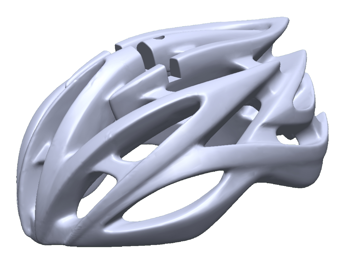
The helmet on the right is depicted in its CAD format, but once saved as an STL; your CAD software will begin to break it down to the triangular mesh, based on your CAD’s STL export format. So, based on my export settings the helmet to the right was converted to the helmet.
below. The helmet below consists of 538,150 surface Triangles and the file size is roughly 27MB.
Ending Thoughts:
Every engineer has gone through a rigorous course called “Integral Calculus” or Calculus II. Integral calculus teaches you about performing functions to essentially describe the area under complex curves – the formulas used to calculate those complex curves are really placing many known shapes “triangles” or rectangles which can be converted to triangles, under the curves, and summing up…that’s why the integral symbol looks like an elongated S. So, fundamentally, the CAD software is performing complex integral calculus to best describe the complex surfaces of your object in a complex binary manner that your complex robot of a 3D printer can understand…complexly.
Complex stuff.